


An alternating current (AC, also ac) is an electric current whose direction reverses cyclically, as opposed to direct current (DC), whose direction remains constant. The usual waveform of an AC power circuit is a sine wave, however in certain applications different waveforms are used, such as triangular or square waves.
Used generically, AC refers to the form in which electricity is delivered to businesses and residences. However, audio and radio signals carried on electrical wires are also examples of alternating current. In these applications, an important goal is often the recovery of information encoded (or modulated) onto the AC signal.
History
A power transformer developed by Lucien Gaulard of France and John Dixon Gibbs of England was demonstrated in London in 1881, and attracted the interest of Westinghouse. They also exhibited the invention in Turin in 1884, where it was adopted for an electric lighting system. Many of their designs were adapted to the particular laws governing electrical distribution in the UK.
In 1882, 1884, and 1885 Gaulard and Gibbs applied for patents on their transformer; however, these were overturned due to actions initiated by Sebastian Ziani de Ferranti and others.
Ferranti went into this business in 1882 when he set up shop in London designing various electrical devices. Ferranti bet on the success of alternating current power distribution early on, and was one of the few experts in this system in the UK. In 1887 the London Electric Supply Corporation (LESCo) hired Ferranti for the design of their power station at Deptford. He designed the building, the generating plant and the distribution system. On its completion in 1891 it was the first truly modern power station, supplying high-
William Stanley, Jr. designed one of the first practical devices to transfer AC power efficiently between isolated circuits. Using pairs of coils wound on a common iron core, his design, called an induction coil, was an early transformer. The AC power system used today developed rapidly after 1886, and includes key concepts by Nikola Tesla, who subsequently sold his patent to George Westinghouse. Lucien Gaulard, John Dixon Gibbs, Carl Wilhelm Siemens and others contributed subsequently to this field. AC systems overcame the limitations of the direct current system used by Thomas Edison to distribute electricity efficiently over long distances even though Edison attempted to discredit alternating current as too dangerous during the War of Currents.
The first commercial power plant in the United States using three-
Alternating current circuit theory evolved rapidly in the latter part of the 19th and early 20th century. Notable contributors to the theoretical basis of alternating current calculations include Charles Steinmetz, James Clerk Maxwell, Oliver Heaviside, and many others. Calculations in unbalanced three-
Transmission, distribution, and domestic power supply
AC voltage may be increased or decreased with a transformer. Use of a higher voltage leads to significantly more efficient transmission of power. The power losses in a conductor are a product of the square of the current and the resistance of the conductor, described by the formula . This means that when transmitting a fixed power on a given wire, if the current is doubled, the power loss will be four times greater.
Since the power transmitted is equal to the product of the current and the voltage (assuming no phase difference), the same amount of power can be transmitted with a lower current by increasing the voltage. Therefore it is advantageous when transmitting large amounts of power to distribute the power with high voltages (often hundreds of kilovolts).
However, high voltages also have disadvantages, the main one being the increased insulation required, and generally increased difficulty in their safe handling. In a power plant, power is generated at a convenient voltage for the design of a generator, and then stepped up to a high voltage for transmission. Near the loads, the transmission voltage is stepped down to the voltages used by equipment. Consumer voltages vary depending on the country and size of load, but generally motors and lighting are built to use up to a few hundred volts between phases.
The utilization voltage delivered to equipment such as lighting and motor loads is standardized, with an allowable range of voltage over which equipment is expected to operate. Standard power utilization voltages and percentage tolerance vary in the different mains power systems found in the world.
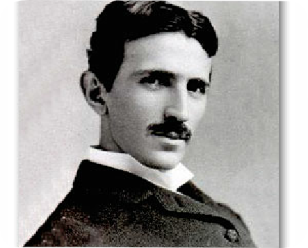
Nikola Tesla (10 July 1856 – 7 January 1943) was an inventor and a mechanical and electrical engineer. Born in Smiljan, Croatian Krajina, Austrian Empire, he was an ethnic Serb subject of the Austrian Empire and later became an American citizen.
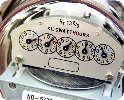
Standard American electric meter.
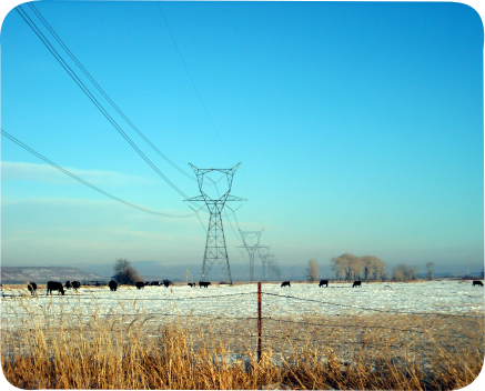
Electrical Grid system uses alternating current becuase of the greater transmission capability of the current over direct current, which losses energy rapidly over distances.
Modern high-
Three-
If the load on a three-
For three-
For smaller customers (just how small varies by country and age of the installation) only a single phase and the neutral or two phases and the neutral are taken to the property. For larger installations all three phases and the neutral are taken to the main distribution panel. From the three-
Three-
A third wire, called the bond wire, is often connected between non-
